

Buyers guide
How much power does a data centre need, and how does that turn into an equipment list?
TL;DR
The data centre power delivery chain has five stages: the grid connection, the primary substation, medium-voltage distribution, low-voltage distribution, and standby generation.
Four items are long-lead: large power transformers, high-voltage switchgear, high-voltage cable, and generator sets. Published figures put large power transformers at up to 4 years and cables at 2 to 3 years (IEA, February 2025). Everything downstream of the low-voltage switchboard can usually be bought inside a normal construction programme.
The European reference architecture for data centre power is EN 50600-2-2, published internationally as ISO/IEC 22237-3. Equipment naming comes from the IEC standards: IEC 60076 for transformers, IEC 62271 for high-voltage switchgear, IEC 61439 for low-voltage assemblies, IEC 62040 for UPS, and ISO 8528 for generating sets.
The line between what your network operator owns and what you own shifts by country and by how much of the connection you choose to build yourself.
1. What does the power delivery chain in a data centre actually look like?
Electrically, every data centre follows the same process: it receives power at transmission voltage, then steps it down in stages to a level safe for IT equipment.
Higher voltage reduces current for the same power, allowing for thinner conductors and less energy lost as heat. This is the reason for the stepped chain. If servers could safely run at 132kV, none of this equipment would be needed.
The five stages.
Stage 1: the grid connection. The physical and legal point where the network operator's system ends and yours begins. Depending on your load and location,, this sits at transmission voltage (400kV, 275kV, or 220kV in most European systems) or distribution voltage (132kV, 110kV, 33kV, 20kV, or 11kV, depending on the country).
Stage 2: the primary substation. This steps grid voltage down to site distribution level. Large power transformers and high-voltage switchgear are located here. It is typically the most expensive part of the chain.
Stage 3: medium-voltage distribution. Moves power from the primary substation to the buildings and the data halls, typically at 11kV or 20kV, through medium-voltage switchgear and cable.
Stage 4: low-voltage distribution. Steps medium voltage down to 400V three-phase, then routes it through low-voltage switchboards, UPS systems, busbar trunking and power distribution units to the rack.
Stage 5: standby generation. This sits alongside stages 3 and 4, taking over when the grid supply fails.
Where the published architecture is written down.
If you want a document to point at in a design review, use EN 50600-2-2, “Information technology. Data centre facilities and infrastructures. Power distribution”. It is the European standard, published internationally as ISO/IEC 22237-3:2021. It covers power supplies to the data centre, distribution within it, telecommunications bonding, lightning protection, and power measurement.
EN 50600-2-2 grades the power system into four availability classes, 1 to 4. Under EN 50600-1, the facility’s overall availability class is set by the lowest of its three rated systems: power distribution, environmental control and telecommunications cabling. A Class 4 power system in a building with Class 2 cooling gives you a Class 2 data centre.
You will also see Uptime Institute’s Tier classification (Tier I to Tier IV) used in commercial documents, particularly in leases and customer contracts. The two schemes are not interchangeable and neither maps cleanly onto the other. If both appear in your documents, confirm which one your obligation is written against.
A terminology trap worth knowing on day one.
In everyday use, “medium voltage” means something between about 1kV and 36kV. IEC does not define it that way. Under IEC convention, anything above 1000V AC is high voltage, which is why IEC 62271 is titled “High-voltage switchgear and controlgear” and IEC 62271-200 covers equipment from above 1kV up to and including 52kV.
PRACTICAL TIP: When an OEM quotes you “HV switchgear” against IEC 62271-200, they may mean 11kV panels, not a 132kV substation. Ask for the rated voltage in kV on every line of the quote. It removes any ambiguity in one step.
Voltages differ by country, and the difference reaches your BoM (Bill of Materials).
The architecture is consistent across Europe, but the voltage levels differ.
Every European system has three bands above low voltage. Transmission sits at 400kV or 380kV, with a second level at 275kV, 300kV or 220kV depending on the country. Beneath that sits a sub-transmission or high-voltage distribution band, anywhere from 45kV to 150kV. Beneath that sits medium-voltage distribution, commonly 10kV to 33kV. Low voltage is 400/230V almost everywhere.
The exact numbers vary, and so does the line between transmission and distribution. The UK runs 400kV and 275kV transmission, with 132kV, 33kV, and 11kV below; 132kV is distribution in England and Wales but transmission in Scotland. France runs 400kV and 225kV with 90kV and 63kV beneath, then 20kV distribution. Section 7 carries the full market table.
Standard voltages are set out in IEC 60038. Regional operators use local variants, and the published national figures are common cases rather than a complete account, so confirm the actual voltage at your site with the network operator before specifying anything.
Primary voltage determines the transformer specification, which is what OEMs price and schedule against. If your portfolio spans the UK, Germany, and the Netherlands, you will not be able to use the same transformer specification everywhere, which limits your ability to standardise and negotiate better terms. Where your sites are within one country or, ideally, one network operator’s area, repeating a single specification is one of the few genuine levers available.
2. What happens at the grid connection point?
The grid connection sets your energisation date, fixes your capacity, and dictates much of your subsequent procurement.
The physical equipment.
At the connection point itself, you will typically find:
A new bay at an existing network substation, or a new grid supply point built for your site. This is usually the network operator’s asset and their procurement, though it may be contestable work you can build yourself.
Metering. Settlement metering to the relevant national code, plus current and voltage transformers to feed it. Instrument transformers are covered by the IEC 61869 series.
Protection. Relays and the associated schemes that disconnect your site if a fault occurs, so a problem on your side does not propagate into the network. Protection settings are agreed with the operator and are not negotiable like commercial terms.
Earthing. The earthing design at the connection point is safety-critical and often emerges as an early-stage surprise cost, especially on brownfield sites.
Switchgear at the point of supply, sized and rated for the grid fault level at that location.
The UK process, as it stands in 2026.
Great Britain is partway through the largest reform of its connections process in decades. The queue was reordered into a gated system: Gate 1 created the initial queue in December 2025, and Gate 2 assesses projects against technical and commercial readiness criteria before issuing firm offers.
NESO and the network companies published a phased offer schedule. Gate 2 Phase 1 offers for transmission and large embedded projects run from mid-May to mid-September 2026, with distribution offers from early July to mid-November 2026. Phase 2 runs from September 2026 into the first quarter of 2027, sequenced by location.
Demand connections such as data centres are treated differently from generation under the reforms. Demand projects are taken to have satisfied the “needed” test automatically, so readiness is the operative criterion. Distribution-connected demand currently sits outside the reformed process, with parallel arrangements under consideration.
Who you apply to depends on where you connect. Transmission-level connections go through NESO and the relevant transmission owner. Distribution-level connections go to the DNO for your region. An IDNO can also build and own the connection assets, which changes who carries the equipment procurement and, with it, the lead-time risk.
These timelines are being revised as the reform programme runs. Check the current NESO position rather than relying on any published schedule more than a quarter old, including this one.
Ireland.
Ireland has moved furthest of any European market in tying grid access to what a data centre brings. The CRU published its decision on connection policy for data centres on 12 December 2025. New data centres must provide generation or storage capacity, on site or locally, matched to their maximum import demand, and must source at least 80% of annual demand from additional renewable generation in the Republic of Ireland, with a 6-year glide path to build and connect it. Previously contracted renewable capacity does not count.
Applications go to EirGrid for transmission connections and ESB Networks for distribution, and are assessed against the specific network location rather than a regional policy. System Operators were required to publish their engagement and connection process by 31 March 2026.
For procurement, this changes the BoM. On-site generation in Ireland is now a condition of connection and a revenue-bearing asset that participates in wholesale markets, which puts generator sets and storage on the critical path in a way they are not elsewhere.
The rest of Europe.
The UK and Ireland are set out above because both have distinctive rules that change what you buy. Every other European market runs its own process, and the operators, thresholds and contestability rules differ enough that a country-by-country summary here would date within a year. Section 7 has a market-by-market table and the four questions to ask in any market your team has not worked in before.
Capacity at the specific location is the first question, not the last. The Netherlands in particular has structural congestion across large parts of the country, and several markets will tell you there is nothing available at your preferred site before any other conversation is worth having. Dutch policy and case law in this area have been moving, so get current legal advice rather than relying on what was true 18 months ago.
And the connection offer is a technical document as well as a commercial one. The technical schedule is where your equipment specification is really set. Protection requirements, metering, earthing, harmonic limits, and power factor obligations all sit in that schedule, and each changes what you buy.
Your network operator is in the same queue.
Signing a connection offer triggers reinforcement works on the network side, which also require transformers, switchgear, and cable. Your network operator sources this equipment from the same incumbent OEMs, drawing on the same limited capacity.
Your energisation date depends on two equipment queues, but you only control one of them.
3. What does the primary substation do?
The primary substation takes power at grid voltage and steps it down to the voltage you distribute around the site.
The equipment, item by item.
High-voltage switchgear. Comes in two forms. Air-insulated switchgear (AIS) is cheaper and takes more land. Gas-insulated switchgear (GIS) is more compact and costs more, and is the usual choice where land is tight, or the environment is harsh. Under IEC, metal-enclosed switchgear up to and including 52kV sits under IEC 62271-200, and gas-insulated metal-enclosed switchgear above 52kV under IEC 62271-203. Circuit breakers are IEC 62271-100, while disconnectors and earthing switches are IEC 62271-102.
One live specification issue: SF6, the insulating gas used in most GIS, is a potent greenhouse gas and is being phased down under EU F-gas regulation. Major OEMs now offer SF6-free alternatives at most voltage levels. Confirm which you are buying, because the two are not always available on the same lead time.
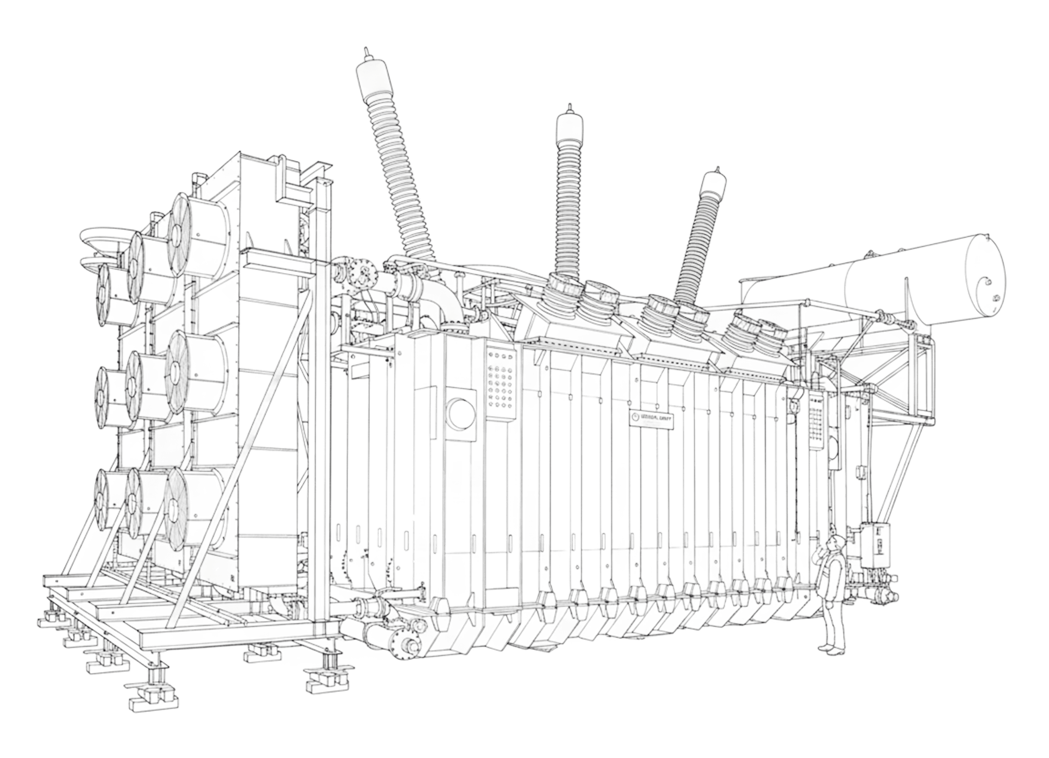
Power transformers. Covered by the IEC 60076 series. This is the single item most likely to set your programme date. The specification points that drive price and lead time are:
Rating in MVA, and whether you are buying one unit or two for redundancy.
Voltage ratio and vector group.
Impedance, which determines downstream fault levels and therefore the rating of everything after it.
Tap changer type. An on-load tap changer (OLTC) is a separate, sourced sub-assembly with its own supply constraints. An off-circuit tap changer is simpler and cheaper, and is only viable where your voltage regulation allows it.
Cooling designation (ONAN, ONAF and so on).
Insulating fluid. Mineral oil is standard. Synthetic or natural ester fluids have a higher fire point and can reduce separation distances and bunding requirements, which sometimes pays for itself in civils.
Noise limits, which on urban and suburban sites are frequently a planning condition rather than an engineering preference.
Loss capitalisation. Buyers who evaluate on loss-capitalised cost rather than purchase price get a different, usually better, outcome over a 30-year asset life.
Protection, control, and auxiliaries. Protection relays, instrument transformers (IEC 61869), substation automation and communications (IEC 61850), surge arresters (IEC 60099), and the DC battery and charger system that keeps protection alive when the AC supply is gone. Individually inexpensive. Collectively, a long list of parts that must all arrive before commissioning can start.
Civil and structural works. Transformer bays, oil containment bunds, blast and fire walls, cable trenches, and access all matter. Large power transformers arrive as abnormal loads, so route surveys, bridge assessments, and police notifications are essential. Sites have lost weeks at the end of a three-year procurement effort, simply because nobody checked if the transformer could physically reach the plinth.
Power installations above 1kV AC are covered by IEC 61936-1, which is the umbrella document for the substation as an installation rather than for individual products in it.
Redundancy doubles your longest lead time.
Most facilities buy at least two power transformers to ensure one can fail or be maintained without losing the load. This is the correct engineering approach, but it doubles your exposure to the longest lead time in the chain.
Ordering two transformers means securing two slots in the same queue, usually with the same OEM. If you have not finalised your redundancy strategy before going to market, you will end up approaching it twice, and the second order will be further back in the queue.
Decide on N+1, N, or 2N redundancy before issuing the first RFQ, not during design development.
Your energisation date depends on two equipment queues, but you only control one of them.
4. How does power get from the substation to the hall?
Once you are at distribution voltage, the job is to move power across the site and step it down again close to the load.
Medium-voltage distribution.
Medium-voltage switchgear. Ring main units and switchboards, usually rated 11kV to 24kV, built to IEC 62271-200. Configured as rings or radial spurs depending on the resilience design. Where this equipment sits inside the building, its arc-fault containment classification matters for room design and the pressure-relief route.
Medium-voltage cable. Cable standards are divided by voltage. IEC 60502 covers extruded-insulation cables from 1kV to 30kV. IEC 60840 covers above 30kV up to 150kV. IEC 62067 covers above 150kV up to 500kV. Cable pulls of any length need route design, jointing and termination work by qualified jointers, and jointer availability is a genuine constraint in several European markets.
Package or unit substations. Factory-built enclosures containing a transformer, medium-voltage switchgear, and low-voltage switchgear in one unit, covered by IEC 62271-202. They reduce site work and commissioning time. They also lock in the design earlier, because you are buying an assembly rather than components.
Distribution transformers. Typically 1 to 3.15MVA, stepping 11kV or 20kV down to 400V. Cast-resin dry-type units (IEC 60076-11) are common indoors because they carry no fire load from insulating liquid. Oil-filled units are usually cheaper and more efficient and are the normal choice outdoors. EU Regulation 548/2014, as amended, sets minimum efficiency requirements for transformers sold in the EU, so the efficiency class is partly a legal question, not just a commercial one.
Low-voltage distribution.
Low-voltage switchboards. Built to the IEC 61439 series, principally IEC 61439-1 and IEC 61439-2 for power switchgear and controlgear assemblies. Air circuit breakers and moulded-case circuit breakers within them are covered by IEC 60947-2. The specification points that matter are the rated short-circuit withstand (which comes from the upstream transformer impedance), the form of internal separation, and whether the board is designed for live maintenance.
UPS (uninterruptible power supply). The UPS covers the gap between the grid failing and the generators picking up the load, which is seconds to a minute or two. IEC 62040 is the UPS series, and IEC 62040-3 classifies UPS by output performance using a three-part code (VFI, VI or VFD). Double-conversion VFI is the data centre norm because it isolates the load from input voltage and frequency variation.
The real decisions here are energy storage and topology. Valve-regulated lead-acid batteries are cheaper to buy and have a shorter service life. Lithium-ion costs more upfront, takes less space, lasts longer, and brings its own fire strategy and insurance conversation.
Rotary UPS using stored kinetic energy remains in use on some larger European sites. Whichever you choose, decide before the building layout is fixed, because the footprint, floor loading and fire compartmentation differ substantially.
Busbar trunking. Overhead busways distribute power along the hall with tap-off boxes above each row, as covered by IEC 61439-6. They cost more than cable but are faster to modify and much easier to reconfigure when rack density changes. In facilities where the load profile is likely to shift, busway typically pays for itself.
PDUs (power distribution units) and remote power panels. Floor-standing PDUs and rack PDUs provide final circuit protection and metering. Rack PDUs are also where per-rack energy measurement usually comes from, which matters for both billing and reporting obligations.
Static transfer switches. Used where single-corded equipment needs a dual-path supply, switching between A and B feeds in milliseconds.
At the rack.
In Europe, IT equipment is normally fed at 230V single-phase or 400V three-phase, delivered on two independent paths (A and B) to dual-corded servers. That has been the stable design for two decades.
It is now changing at the high-density end. Racks running AI training workloads draw far more power than a traditional rack, and the industry is actively working on higher-voltage distribution to the rack and on DC architectures. This part of the design is moving quickly, and the standards have not settled. If you are procuring for a facility that may host high-density workloads, treat the rack-level design as a decision to keep open rather than one to fix early, and put the flexibility into the busway and the floor plan rather than into the equipment.
Each conversion in the chain loses some energy as heat. This is why efficiency class appears on transformer, UPS, and switchgear specifications, and why two similar quotes can differ by hundreds of thousands of pounds over the asset’s life. Always ask for loss figures at realistic load, not just at full load.
5. Where does backup and standby generation sit?
Backup power does two separate jobs, and they need different equipment.
Ride-through covers the seconds between the grid failing and something else picking up the load. That is the UPS, described above.
Standby covers the hours or days after that. That is generation, and it sits electrically upstream of the UPS, connecting at either the low-voltage or medium-voltage boards depending on the size of the facility. Mid-size and large sites usually parallel generators at medium voltage, because the cable and switchgear required to parallel several megawatts at 400V become impractical.
The equipment.
Generator sets. Reciprocating engine-driven generating sets are covered by the ISO 8528 series. ISO 8528-1 defines the rating classes, and the distinction matters commercially. Emergency standby power (ESP) is rated for use during a utility outage with no overload capability. Prime power (PRP) allows unlimited hours with variable load. Continuous power (COP) allows unlimited hours at constant load. Buying an ESP-rated set and then running it commercially, for example in a grid-support arrangement, is a specification error with warranty consequences.
Paralleling and synchronising switchgear. Controls multiple generators sharing load and synchronising to each other and, where permitted, to the grid. A separate procurement with its own engineering content.
Fuel systems. Bulk storage, day tanks, pipework, bunding, and spill containment. Diesel remains standard. HVO (hydrotreated vegetable oil) is increasingly specified in Europe to reduce reported emissions, and needs confirmation that the warranty covers it from the engine OEM.
Load banks. Required for commissioning and for periodic testing. Often forgotten in the early budget and then rented at a premium.
Battery energy storage. Increasingly present alongside or instead of some generator capacity, particularly where it can also earn revenue from grid services. Grid-forming inverters have made this more viable than it was five years ago, though for long-duration outage cover, generators remain the default.
The regulatory trap in generator procurement.
Procurement teams new to power equipment are most often caught out here.
Standby generators are combustion plants, and combustion plants are regulated by thermal input, not electrical output. As a rough conversion, engine thermal input is roughly three times electrical output, so a 2MW generator is around 6MWth.
In the EU, the Medium Combustion Plant Directive (Directive (EU) 2015/2193) covers combustion plants from 1MW to 50MW thermal input and sets emission limits and permitting requirements. Larger plants fall under the Industrial Emissions Directive. Aggregation rules, derogations for emergency-only plants, and the operating-hour limits that go with them vary by member state and by how the directive was transposed locally. The UK operates its own regime for medium combustion plants and specified generators under the Environmental Permitting Regulations.
We outline this regime rather than give a definitive account, because the detail is country-specific and has changed since the directive was transposed. Have an environmental consultant in your jurisdiction check it early.
Emissions compliance alters the generator specification. Aftertreatment, stack height, testing hours, and permitted running regimes all affect what you order, what it costs, and how long it takes to arrive. Finding out about permit conditions after placing the order is far more expensive than discovering them in advance.
6. Which of these are long-lead items, and which are not?
Four items sit far outside a normal construction programme. Everything else can be managed within one.
What the published evidence says.
The IEA’s February 2025 report ‘Building the Future Transmission Grid’ surveyed leading industry participants and found that procurement takes up to 4 years for large power transformers, roughly twice as long as in 2021, and 2 to 3 years for cables, with direct current cables extending beyond 5 years. Over the same period, transformer prices rose around 75% in real terms, and cable prices nearly doubled since 2019.
For switchgear, generator sets, and UPS, published lead-time figures vary widely and most of what is available online is unsourced. Get written lead times in every quotation, treat them as a commercial term with a validity date attached, and re-confirm them at order.
The rough ordering.
title
title
title
Keep reading:
Build the market, not just the factories: Opna's market infrastructure blueprint for the critical power supply chain.
Sources.
Ofgem, "Consultation Curate - Demand Connections Reform", 29 July 2026: https://www.ofgem.gov.uk/sites/default/files/2026-07/Proposed-data-centre-connection-reforms-curate-consultation-document.pdf
Addleshaw Goddard, "Ofgem's Curate Consultation: What it means for Grid Connected Data Centre Projects in Great Britain", 2026: https://www.addleshawgoddard.com/en/insights/insights-briefings/2026/infrastructure-projects-energy/ofgems-curate-consultation-grid-connected-data-centre-projects-great-britain/
Terrapin Construction Group, "Switchgear, Transformer, and Generator Lead Times in 2026", June 2026: https://terrapincg.com/news/switchgear-transformer-generator-lead-times-2026
S&P Global Commodity Insights, interview with Andreas Schierenbeck, CEO, Hitachi Energy, 5 January 2026: https://www.spglobal.com/energy/en/news-research/latest-news/electric-power/010526-interview-no-peak-demand-in-sight-for-booming-power-grid-demand-hitachi-energy-ceo
Utility Dive, Siemens Energy Q3 FY2026 results coverage, 10 August 2026: https://www.utilitydive.com/news/siemens-gas-turbine-backlog-nears-70-gw-as-company-expands-manufacturing/827390/
GOV.UK, "Lanarkshire AI Growth Zone secures £300 million investment as Dell establishes Scottish base", 18 August 2026: https://www.gov.uk/government/news/lanarkshire-ai-growth-zone-secures-300-million-investment-as-dell-establishes-scottish-base
NESO, "NESO implements electricity grid connection reforms", 8 December 2025: https://www.neso.energy/neso-implements-electricity-grid-connection-reforms-unlock-investment-great-britain
Eurelectric, "Grids for Speed", 2025
Wood Mackenzie, Q2 2025